Hello again!
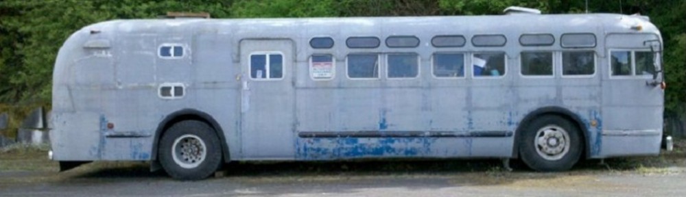
In the mad-rush to get things finished for a trip out the Alvord Desert this week, I was able to get the front rack of The Ghost finished and some new solar panels mounted. I scored a sweet deal on craigslist for some 60-cell (28-32V nominal) These are 250W 5’5″ x 3’3″, aluminium frame panels constructed for home power installation. I built under-supporting frames to help bear vibration load since the frames are not designed for mobile applications.
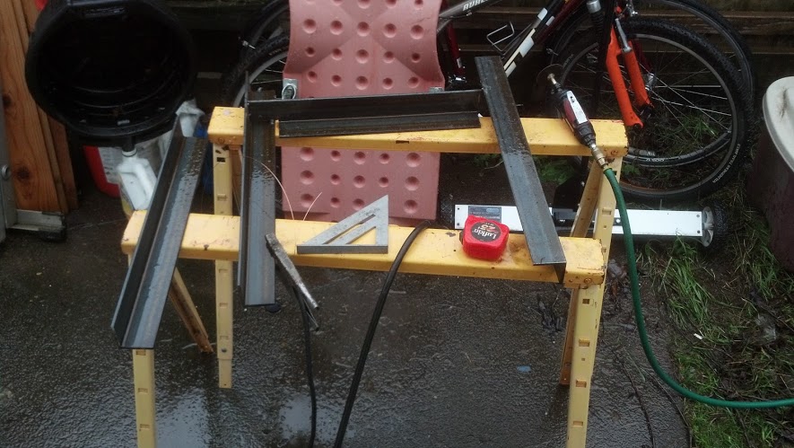
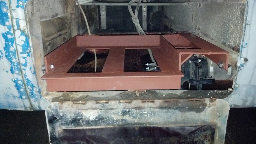
I started by extending the existing rack I built last year farther forward to support the panels. I constructed it out of materials and in such a way that it is actually rated to support humans. The wind load of the panels could be quite substantial in high winds or at high speeds.
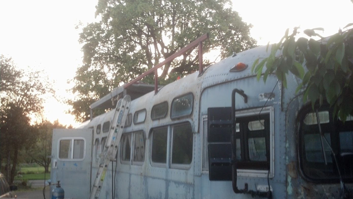
Beginning to build the support rack
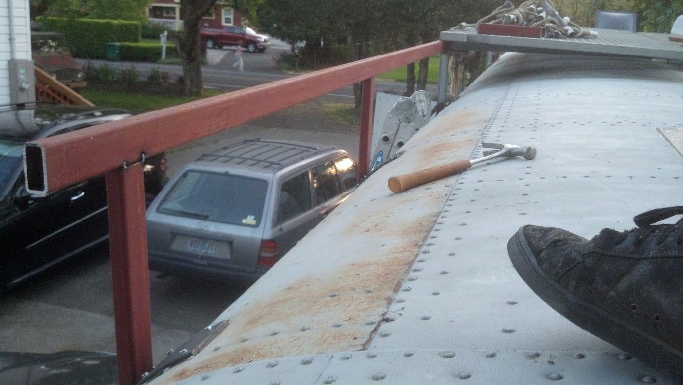
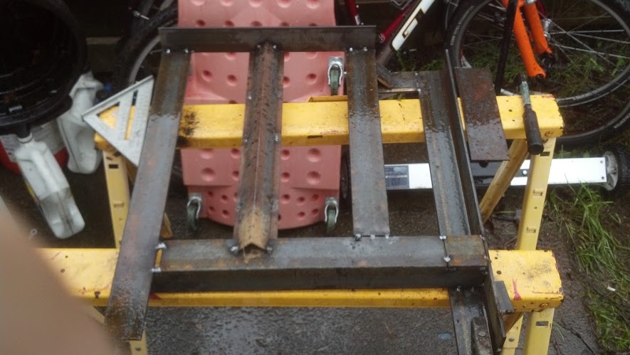
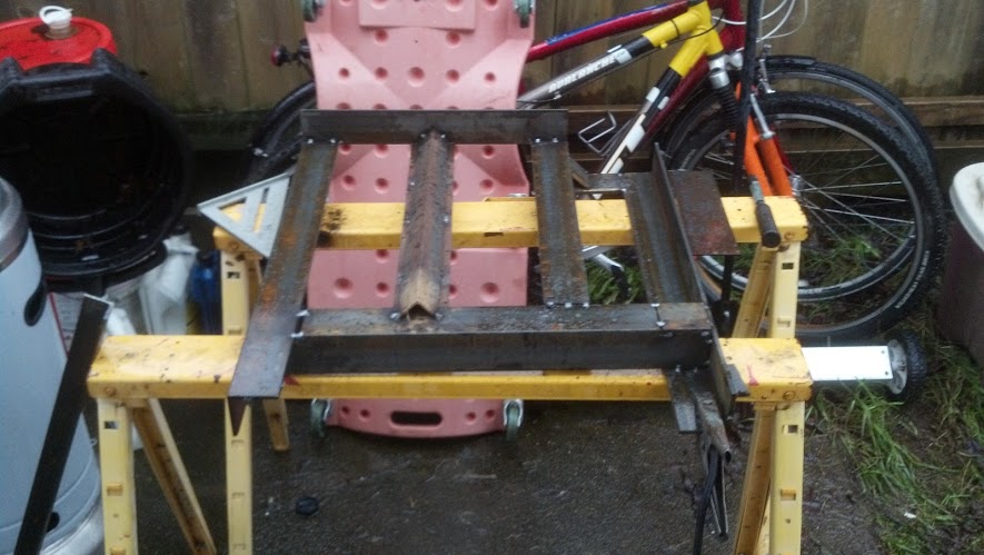
Rooftop View Tack Welded
Once the rack was finished, I welded some extra support pieces onto the spreaders to support the panels in their odd locations. I had to choose this odd layout to allow the roof vent to open (power vent lid) and also not hang over the side of the coach too far or cover the horn/antennas/etc. This configuration allows me to see the edge of the panel in my drivers side mirror and is still inboard of the two air-conditioning units.
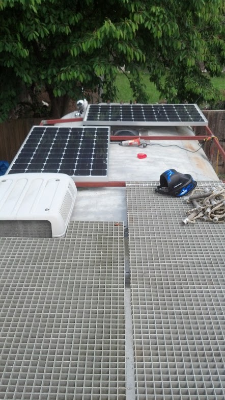
Solar panels in their proper locations preparing to mount.
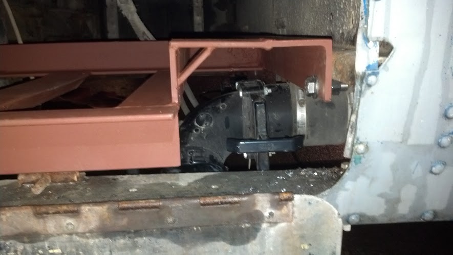
The panels are mounted at four points each using 8 self-tapping screws into the main frame members. The other side of these brackets are welded to the rack-frame of the coach. This seems to be providing a very stout level of connection and hopefully will give the panels the longest life.
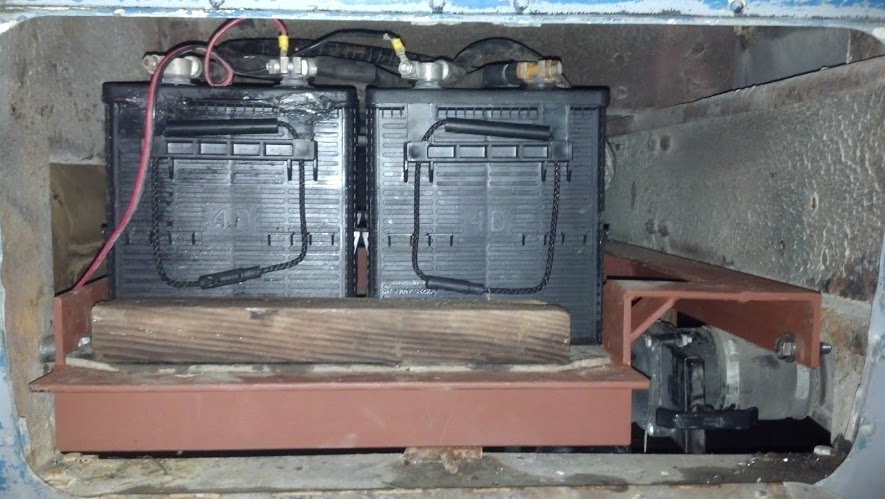
The two panels are connected in parallel and directly feed a 20A 12/24V charge controller. This power is then fed into the temporary 24V sealed lead acid battery bank which is either used directly (for 24V appliances and later the large inverter) or indirectly though a 24V to 12V 360W converter. With this amount of solar combined with our desired eventual inverter/battery bank, we could actually run a small amount of solar powered air-conditioning for the morning hours while we wanted to sleep at events like BurningMan, etc. Realistically in Oregon the amount of power generated is not significant in comparison to the cost of power from a utility, however in the desert or off-grid this starts to be a large win. My intention is to eventually augment the DC power system with a 24V 150A+ alternator/propane generator combination. I have a ~30gal propane tank slated to be installed into the coach as well which will supply fuel to the stove/oven as well as the generator.
Check back soon for more updates!