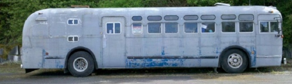
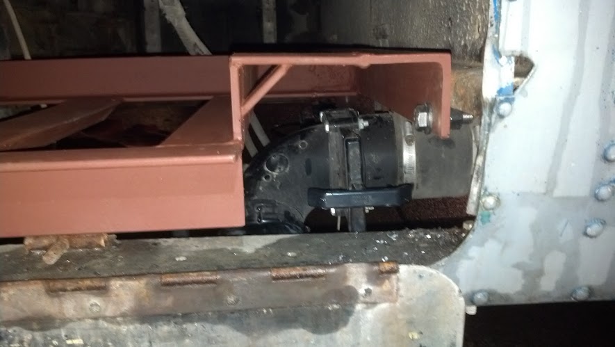
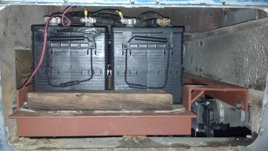
Hello again! Recently the service brake valve (a D1) that I rebuilt many moons ago started leaking again. Due to the age of the valve, the age of the rebuild kit, and the general lack of available parts for such an item on the open road, I decided it was time for some changes. While plugging around under the bus, I found that there was some equipment (from the city transit days) that was also leaking. This valve (all torn apart on the bench) was the culprit:
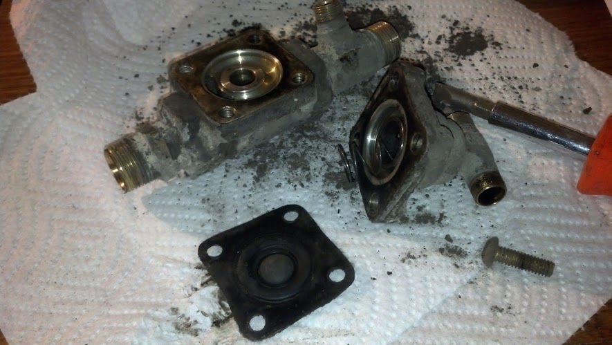
Unknown Valve Torn Apart
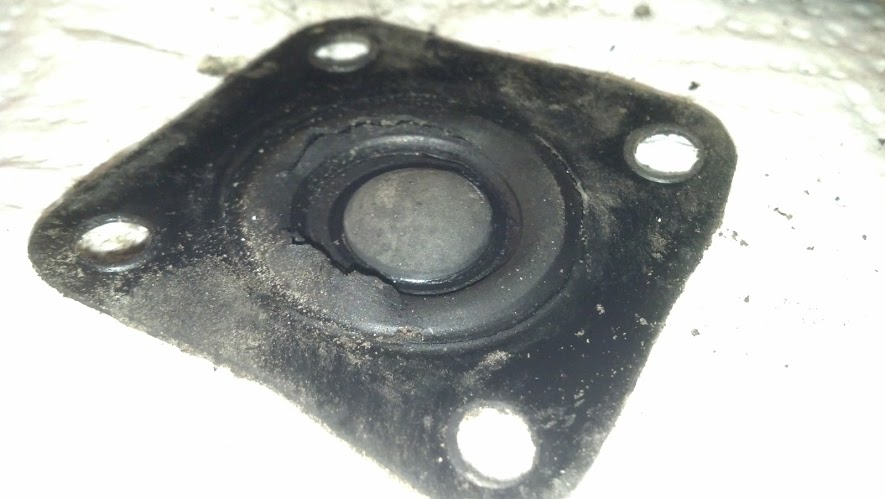
Failed Rubber Bits
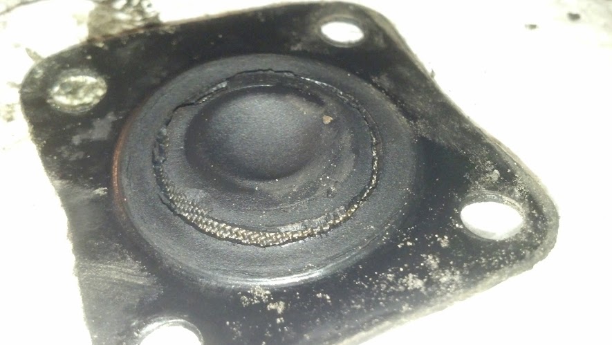
More Failed Rubber Bits
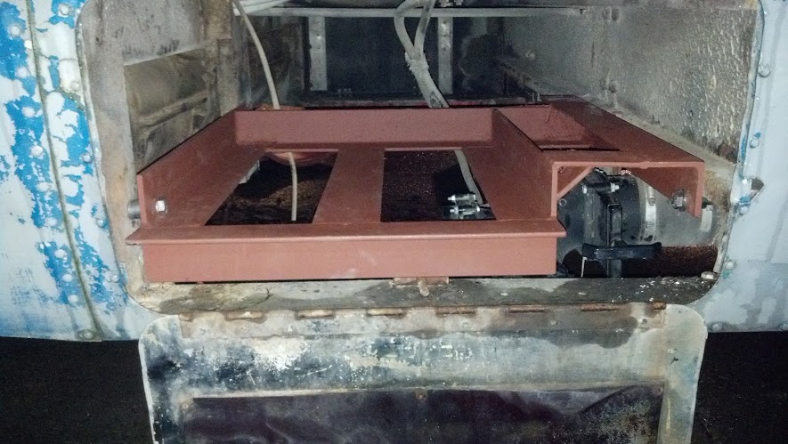
It took some heavy researching to figure out what this valve did. It was installed between the main air-brake service tank and the foot valve in the main pressure line. It also received signals from ‘somewhere’ that I could not find the other end of. The other side of this same “unknown” line went off into a dual input check valve in the rear brake circuit. As much as I boggled my mind (and hit the books) I could not figure out why you would want to interrupt the brake signal. Finally I did some poking around in my New Look book (which I ended up with for $10 off ebay) and found that it was an emergency brake valve (before spring brakes existed). The purpose of this valve was that if there was a massive leak at the foot valve, a small hand-valve at the operators left could be thrown into “emergency mode” which applied air to this valve, closing off air supply to the foot valve. Then, this same signal was sent to the 2-way check valve for the rear brakes, applying the brakes fully and (hopefully) stopping the coach. Crude and rude, but I’m sure it did work (yet was probably never used). It still required air in the main tanks, something that spring brakes do not require (absence of air applies the brakes in an emergency). So, out came the valve, but I was left with a bunch of air-lines to cap/patch/re-connect.
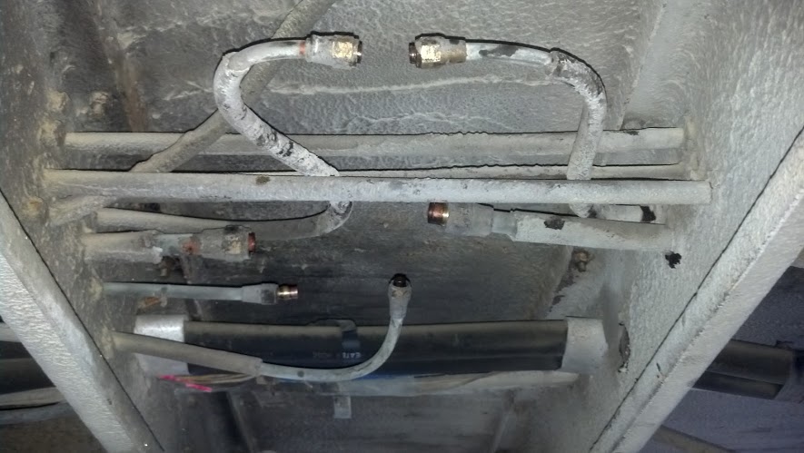
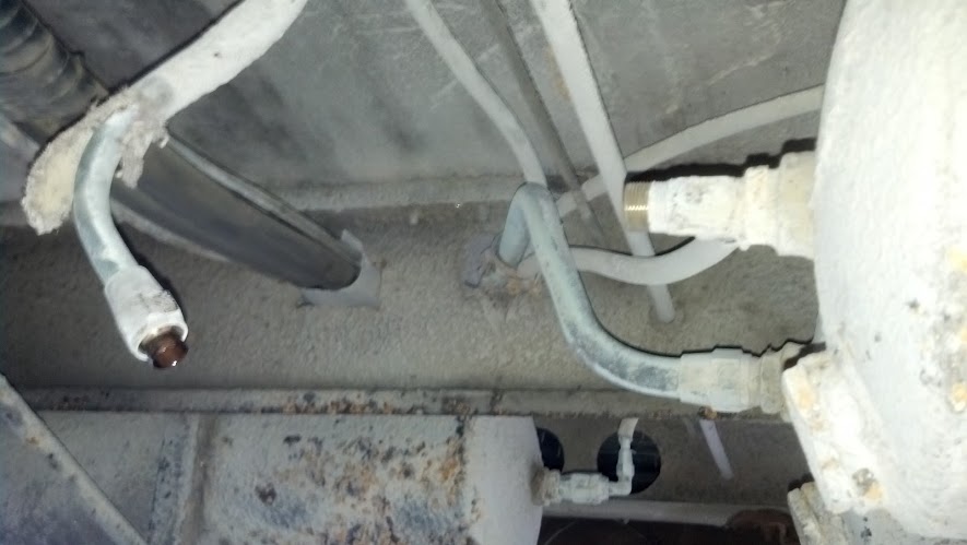
Lots of Air-lines!
The next step was to re-connect the service brake pressure line. Of course this was originally heavy gauge copper tubing (at some expense!) but the popular choice is plastic air-brake rated tubing and compression fittings. Removing the old copper line was a real chore (almost too stiff to bend, and grommets installed where it passed through the frame members. I disturbed a LOT of dirt. I out-fitted both ends (valve and tank) with the proper ends and installed a piece of blue 1/2 line.
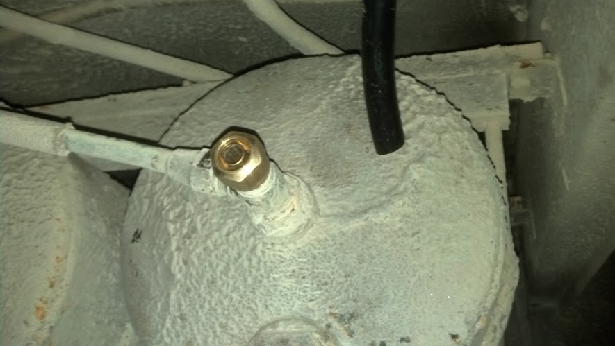
New fitting on the tank end.
Removing the Copper above the front axle
Removing the copper at the tank end
More copper removal
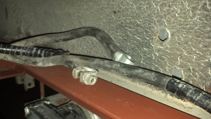
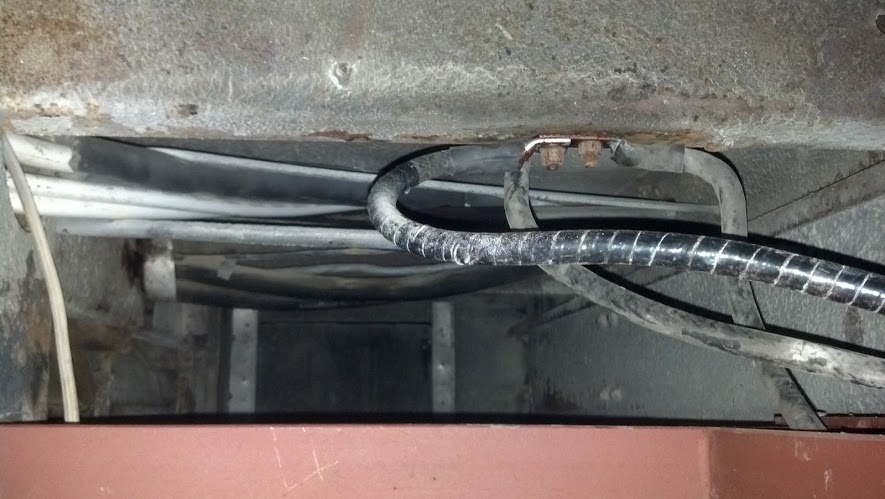
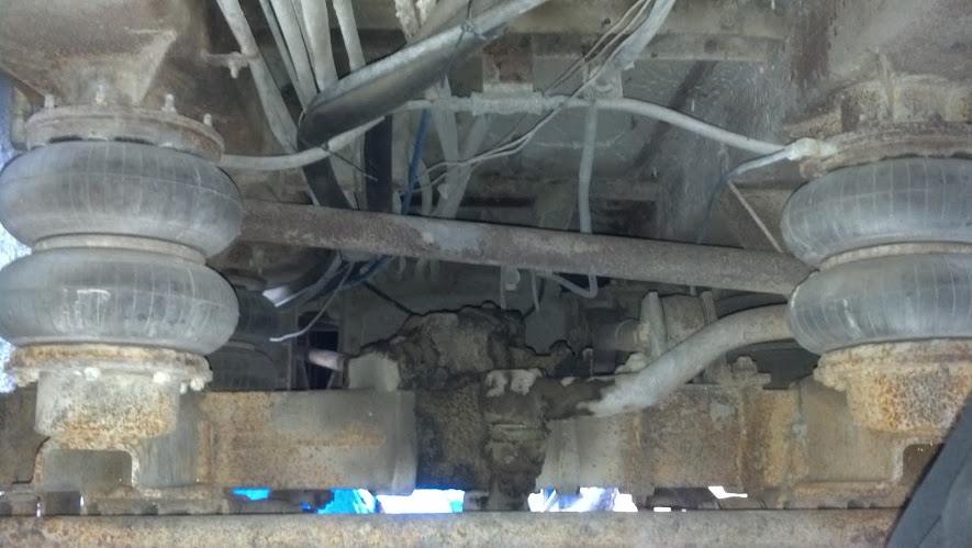
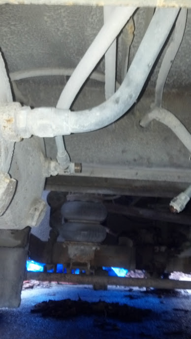
I needed to reconnect the air brake signal line to the rear brakes once the 2-way check valve was removed. I did some fancy footwork with some fittings and gently bent the copper line to make the connection. You cannot kink this material or it will leak and a leak at this junction would be VERY dangerous.
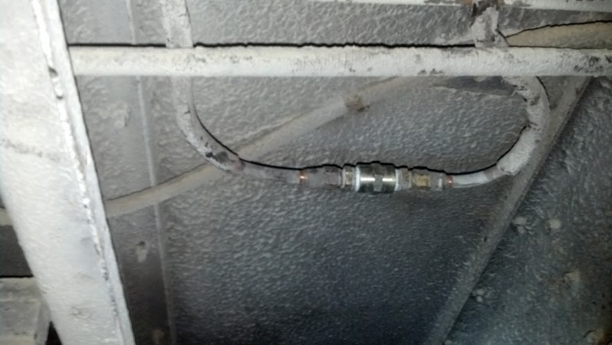
Reconnected signal to rear brakes (removed the 2-way check valve)
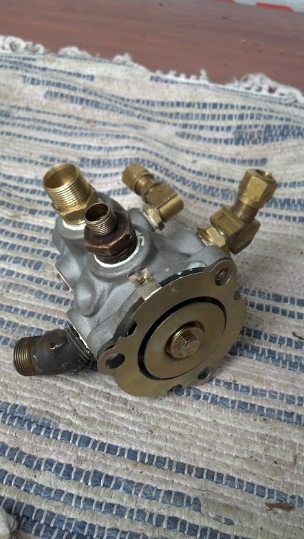
Next on the slab was replacing the service brake foot valve up front with the new E3 I purchased of e-bay. Newer valves than this have multiple inputs however The Ghost only has a single supply air-tank system (even though it is two tanks, they are tied together, one wet, one dry). The E3 is a close replacement to the D1 and is available at most heavy truck parts places so it was an easy choice. Earlier valves in the D series have the potential for being set up for city bus service, and thus do not give the operator the option of 100% air brake power (injury to passengers a large possibility without seatbelts). Modern day with modern tires/non-commercial driving means I want the aggressive brakes if I need them.
I purchased a new E3 valve as well as a new treadle + plate assembly off of e-bay (the E series bolt pattern/size is FAR different from the D series). This required welding up the old hole in the floor so that it could be drilled for the new bolt pattern/etc.
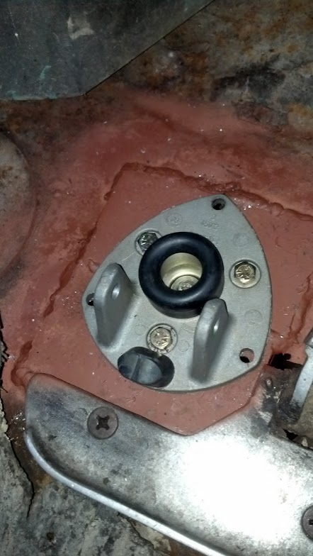
Once this plate was installed, the center hole and mounting holes could be drilled. The E3 valve was set up with the proper fittings in the proper directions to allow for existing brake line connections. I also added a supply line to go directly to my spring-brake emergency valve as well as an application pressure port to go directly to the dual-needle gauge in my dash.
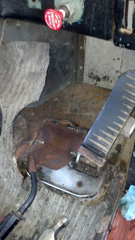
I then mounted the plate (after removing the treadle) directly through the coach body down into the E3 valve. Holes are misaligned here because I left ‘wiggle-room’ in all mounting holes to assist in fine alignment.
Lastly I reattached the pedal assembly and installed some 5/16 bolts in the outside perimeter to assist in keeping things tight.
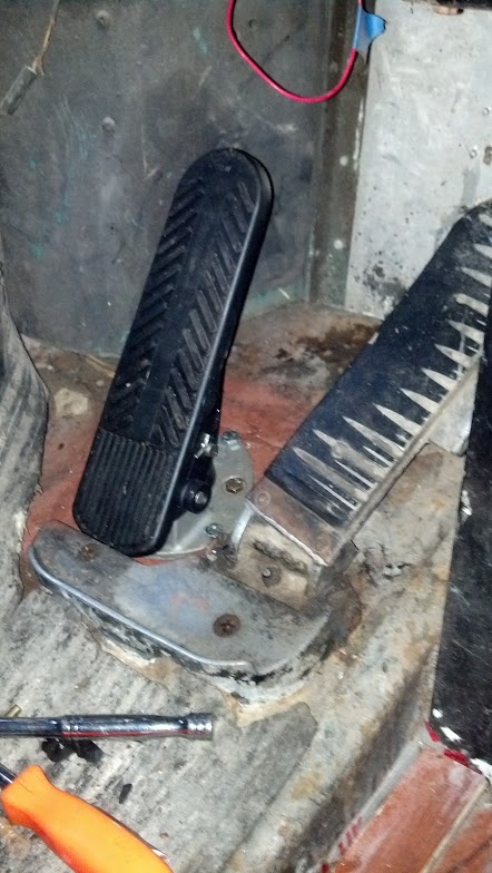
We will see how the new brake valve feels on the road…however so far it is looking fairly promising. The high angle of this pedal assembly can be adjusted with some lathe work on the back-roller however I may keep it like this. Getting full 100% application before was a bit tricky (usually required me to toe-into the pedal). Considering the light amount of driving that The Ghost gets these days, I suspect this pedal assembly will outlast the rest of the coach.