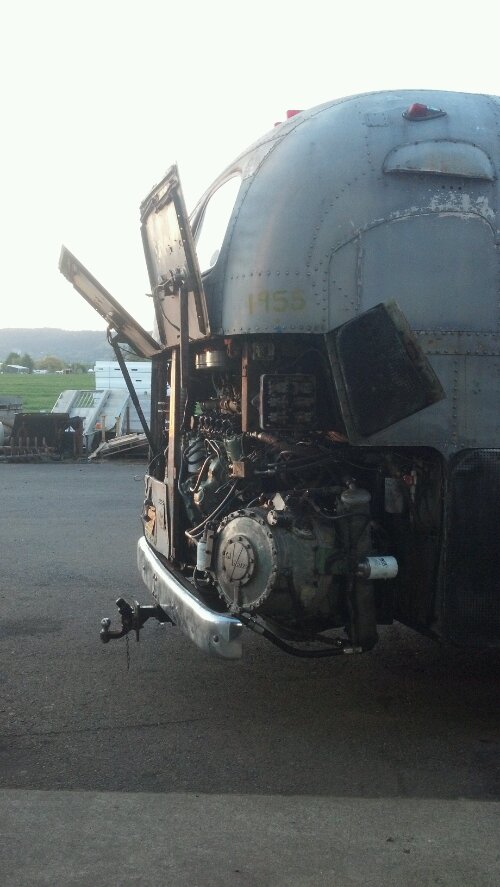
Major Bummer!

The new transmission, on the verge of being installed, reared it’s ugly head and showed it’s true nature………it’s the wrong ratio!

It happens to be one of the most rare VS2-8 models…and there’s no way to tell unless you drive the bus or drop the pan. Unfortunately it’s the center bevel gear ratio so it’s not really worth changing on an otherwise good transmission.

So the game plan is to take the good parts (overdrive gears, clutches, oil pump, etc.) and move it into the busted transmission.

Unfortunately it means more work….but we shall prevail!

More soon.

VS2-8 Repair Round TWO!

So, it broke again.

On our way back from Reno, NV (working after the 4th of Juplaya Trip), we lost overdrive just before Susanville. The feeling and the sound was the same. Large pow, and left with only 1st and 2nd gear. It was the middle of the night on a road that didn’t allow safely parking a 8ft wide 35ft long bus enough to have a look-see at what just happened. I did a visual, nothing was horribly wrong externally, so we continued on.

Fast forward to this week, I’ve been preparing to remove the transmission from The Ghost to determine the fault and drop in the replacement transmission! I recently acquired another VS2-8 from a gentlemen in Kelso, WA out of a Colorado (Mountain Metropolitan Transit) New Look T6H-4523A. The clutch packs look to be in sound shape (better than mine) and the internals were EXCEPTIONALLY clean. Assuming nothing alarming rear its head before installation, this will be the future transmission for The Ghost.

The reason I pursued an entirely new transmission was two fold. First, the parts to fix The Ghost’s VS2-8 (failed round two) are near impossible to find. Secondly, there may be a compound issue with low MAIN pressure on the transmission, which could be aggravating the lack of lubrication issue. Either way, I will be installing my sensors (two temperature sensors and one MAIN pressure sensor) along with the lock for 2nd gear (for descents with Jacobs brakes and climbing large hills).

To make this new transmission work, I will need to adjust the gear end-play from 0.250″ to .050″ or less. This large gap caused a bypassing of lubrication oil of the planetary gear driven plate…eventually leading to a failure of the bearings/bushings. I will be building a small spacer to insert into the transmission stackup to close this gap and hopefully solve the problem for good. This of course is the repercussions of installing a VS2-8 (designed for a deep bellhousing 8v71) on a 6-71 (with a shallow bellhousing) with dual spacer rings.

I also learned (by acquiring my VS2-8) that the factory setup on a 8v71 uses about 1/2 to 2/3 the number of bolts to hold the transmission to the engine that I am using in my setup, WITHOUT a external support on the end of the transmission. I have already built a support (using a motor mount rubber for a Kennworth tractor) so this should be plenty of support to keep the transmission attached to the engine.

Outside of adding this spacer, and re-installing with the new transmission, things should go rather smoothly. I recovered all of my old (undamaged) fluid so I could put it into the new transmission. This is similar to the fluid required for wet clutch driven heavy equipment (like bulldozers).

Over the next few days I should have the spacer built and be back to re-installation. Hopefully everything is ready for a shakedown run to NorthWestMogFest 2012 then shortly after down to BurningMan 2012!

Thanks for checking in!

VS2-8 Transmission O/D Repair – Finished! & Powertrain Update

Well, it’s been multiple weekends and week nights working hard to get it fixed, but the VS2-8 transmission in The Ghost is now back to operational status.


A few short (<5mi) test drives were performed however with an unfinished exhaust system, things are a little too loud to be driving far. All three ‘gears’ were fully functioning and after topping off the transmission fluid (being careful not to overfill) shifts were firm.

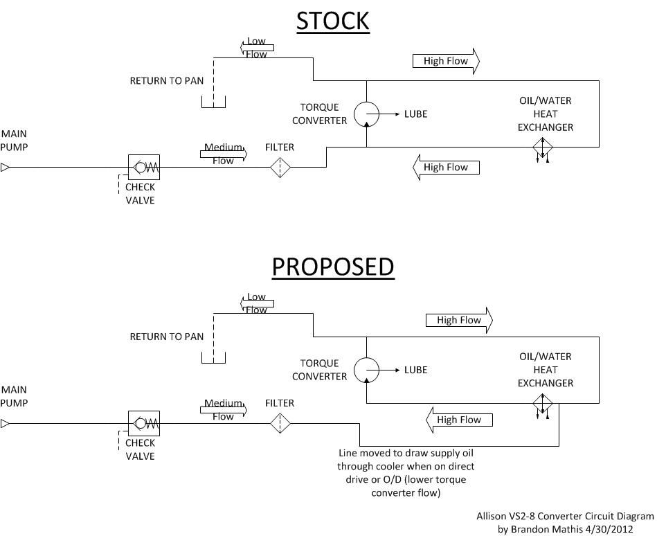
There still remains the need for a microswitch on the throttle linkage to enable the soft down-shift solenoid for O/D to direct drive. I also want to fine-tune the shift point into O/D as currently the switch happens at about 40MPH and I would prefer it to be closer to 52MPH. I am also planning to install a small fluid/air transmission cooler and some valves for switching between O/D and Direct Drive (manual mode).

Another large hurtle overcome was getting the engine power up to rated output. Apparently making the timing adjustment as well as re-adjusting all injectors/exhaust valves with doing a full rack run/setup procedure really brought the power output up. The ‘new’ governor cover with shutdown lever that I had been fighting (and discovered was limiting fuel travel) had been adjusted to no longer interfere. With this fixed, the rack tuned normally and the idle, high speed, and full fuel adjustments were 10 times easier. Seat-of-the-pants power output feels considerably better than before. With overdrive fixed, MPG should improve as well.


The positive to negative ground conversion is going well. The generator and the regulator (stock) both operated properly once I re-polarized the generator with negative ground. The dash gauges indicated charging status and everything except the positive ground gauges I disconnected is still working. I still need to fabricate a dash, re-wire the heater coolant pump motor (swap wires), and install all the engine/transmission gauges/speedometer. It appears there will be 1 speedometer gauge + 8 aux gauges spots:

  • Speedometer (0-85MPH)
  • Engine Oil Pressure (0-80psi)
  • Engine Water Temperature (0-250F)
  • Fuel Level
  • Transmission Temperature (0-400F) – 2 senders
  • Transmission Pressure (0-150psi)
  • Air Pressure (dual needle, indicate tank + application)
  • Charge Current (stock for now)
  • 1 slot left for a 2nd air pressure gauge if I go dual circuit air brakes

This weekend the plan is to fit the 5″ exhaust + muffler and route properly through the bulkhead. a 4″ to 5″ adapter is used at the industrial manifold (4 bolt) then it travels down along block, turns forward towards the bulkhead, passes through (need to cut a large hole) and bends to meet the muffler (if it won’t fit before this) and then finally dumps on the drivers side just behind the rear wheel with a 5″ turn-down. Makes for a total of ~170 degrees of 5″ mandrel bend (minus turn-down). The muffler is a straight-through resonator (Walker 21835). It will be a little loud, however I did not have enough space for a full size can in 5″ and I’d rather have less restriction than quiet exhaust (30ft from the drivers seat). I may fashion some sort of adapter to install on (or in place of) the turn-down for on-playa use to prevent stirring up playa dust from exhaust flow.


Another time lapse video from last nights work:

http://youtu.be/sWGKtlHKt-g

A photo before I put the valve cover and corner support rod back on for final road test.

image

VS2-8 Transmission O/D Repair – Day 3 & 4

Another weekend, more things checked off the drivetrain list.

The big project for this weekend was to prepare the engine for the transmission reassembly and reassemble the transmission splitter overdrive clutch pack and planetary to make sure there were no hidden problems waiting to be discovered.


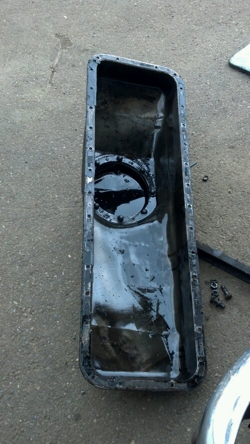
Part of removing the end housing off the engine is needing to replace the (leaking) oil pan gasket. This involves removing the oil pan from the coach, cleaning, and reinstalling with a new gasket. Seems easy however the maze of underbody cribbing and structure keep the puzzle adequately difficult. It was also suspected that there was a bunch of foreign material in the oil pan, after discovering the chunk of material wedged up against the main crank gear from an old air compressor drive failure.


Here is a photo of the oil pan just after removal. You can see the amount of foreign material in the pan (which should only contain motor oil)
image

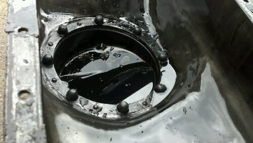
Here is a close up photo of the sump. Note the lack of cleanliness!
image


While in this area, I decided to remove the entire exhaust system to allow for the installation of my much simpler and (hopefully) better flowing 4-5″ exhaust system. These, shy of the flex, are probably stock setups. Both of the brackets that hold the mufflers to the oil pan area were loose, causing wear points on the oil pan (eventually would have worn through the pan, causing a massive leak). The mufflers themselves were starting to show signs of wear as both input and output pipes were starting to rattle loose and leaking exhaust. Time for replacement.
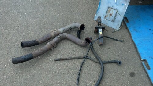
image


Here is a photo of what you often don’t see. The air-box cover has been removed (to replace the gasket) and the governor housing, flyweights, water pump, and blower end housing to allow for replacement of a gasket that was leaking oil. I was in here recently (August 2011) to inspect issues with the governor when I discovered the water pump drive had failed. Unfortunately I didn’t have the correct gasket to do the job, so some Three Bond + Gaffing Tape saved the day for the trips. Upon R&Ring this area, I found that there was yet ANOTHER piece of water pump drive plastic laying in the sump where it didn’t belong. Apparently it had been hiding behind something and didn’t get removed when I replaced the drive. Bottom left is oil to water cooler, and bottom right is the oil filter housing.
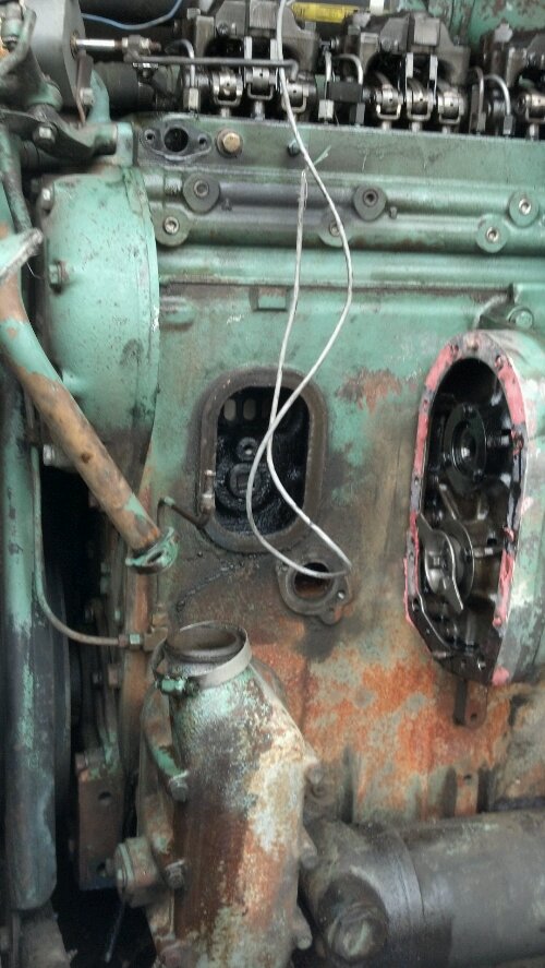
image


Here is a photo of the bottom of the engine (oil pan removed) you can see the oil pickup tube as well as the main bearing caps and connecting rods. These parts are NOT small. The dipstick is visible on the right side of the photo.
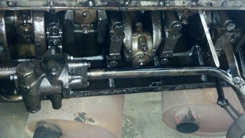
image


This is the material that was stuck in the oil pickup screen. There were many more small particles stuck in the screen itself (not visible here). Fortunately this piece is EASILY cleanable and accessible without removing the whole oil pan (a lower sub pan removes for easy access). The Ghost has a full flow oil filter so luckily none of this stuff made it into the bearing surfaces.
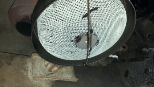
image


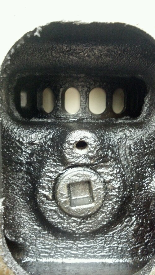
Here is a photo in the air-box with the cover removed. You can see (through the air intake holes) the skirt of the piston. It is in fairly good shape. This space is showing the miles but there is no accumulation of moisture which means the air-box drains are clear. This space is pressurized at all times the engine is running to force air out of the combustion chambers on the down stroke (end of power and beginning of exhaust). This is a 2-stroke diesel engine (every stroke of the piston is a power stroke).
image


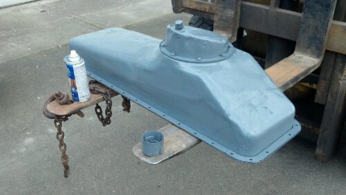
Although this LOOKS Alpine Green, it is actually dark grey paint that I happened to have on hand to paint the paint-less gross oil pan, post cleaning.
image


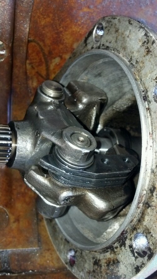
Here is a close up shot of the governor housing flyweights. These flyweights, in conjunction with the springs in the governor box, regulate engine idle speed and maximum engine RPM. They are fed rotational energy off the end of the blower housing (just above the water pump).
image


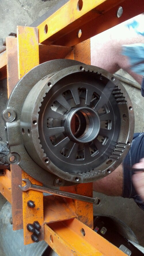
Here is a photo of the splitter overdrive clutch housing being assembled. The top of this stack is the bellville spring which translates the piston movement into an actual clutch pack movement (and thus, a shift).
image


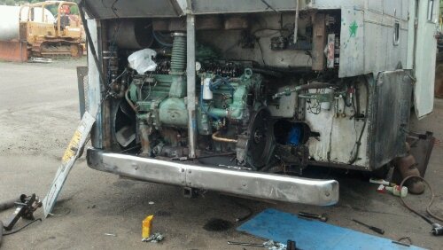
A photo of the now MUCH cleaner engine after hours of pressure washing. Of primary ‘nasty’ was the engine mounting points below the transmission and the subframe components. I also discovered that my radiator was 1/3 plugged with foreign material in the cooling fins. Some Castol Superclean + HOT pressure washer water cleared things outs nice (don’t do this at home, you likely will damage the radiator fins). It is amazing that the engine didn’t overheat more readily with the amount of plugging it was experiencing. A minor oil leak at the oil pan and compressor housing caused most of the engine to the right of the roots blower to be coated with dirt + oil + playa dust so thick that only the high pressure spray would tear it loose. The engine block actually now needs a good coat of Alpine Green to finish it off.
image


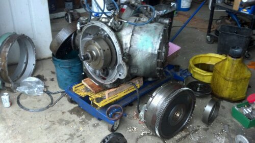
Here is a progress photo of the transmission after installing the splitter overdrive clutch pack. This setup is now ready for the planetary + outer gear before installation. Some plumbing rework will be done as well as dropping the pan to gather all the last metal bits and whatnot that fell down in there. The factory installs a large magnet in the pan so I’m expecting that to be quite built up with shards. The flywheel, with the new bushing installed in visible in the bottom right side of the photo. The two spacer rings required for a 6-71 to VS2-8 mating are visible on the left of the photo.
image


It was a very productive weekend and after a few more hours of cleaning up the last bits, the transmission should be ready to install and start building the supportframing that I have needed to build all this time. A medium size external oil cooler will also be fitted to help keep the transmission cool in the direct-drive/over-drive mode where not much fluid passes through the cooler.


More soon.