Dash Removal

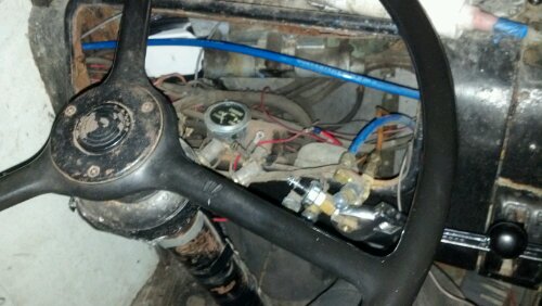
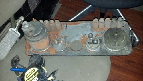
Well the day is finally coming to upgrade the dash in The Ghost to allow for more gauges, newer priorities, and less incandescent bulbs. I Removed all the gauges from the dash (the only decently working ones being the air pressure, engine charge indicator, and water temp) and all the indicator lights (many for city bus service…long disabled). My hope is to continue using the charge indicator (shunt DC current meter) however eventually switching over to a voltage meter would likely suffice


This was a fairly emotional moment…tearing one of the few completely stock pieces of The Ghost out…like gutting the heart out of an animal. I take ease in the fact that it will be replaced with a nice milled piece of aluminium with 9 gauges sitting front and center. I am now in the process of tidying up the wiring all the way back to the junction panels to allow for a much tidier behind-dash condition. The long broken speedometer system will be abandoned in favor of a newer VDO pulse sender. All other gauges (other than air) will be routed electrically through a new 15 conductor cable to the rear of the coach to new senders placed all over the engine/transmission/etc. I also will be using this cable to run a few signals for engine/transmission devices (Jake Brakes, Neutral Solenoid, Direct-Drive Lock).

I am also moving over the maxi-air-brake valve (parking/emergency brakes) a little closer to the driver position to allow for less air-lines running behind the dash and to aid in dash removal for service. I also removed the very old AM/FM 8-track radio even though it still works. I am tired of looking at that ugly thing hanging out of the dash.

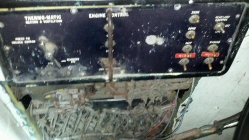
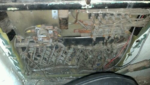
For perspective of the magnitude of this project, have a look at these photos:


While it would be easy to just gut everything and start over…this system is actually fairly decent (including self resetting circuit breakers, large gauge conductors, shrink wrap, and labels). I will slowly transition over to the new wiring but will be keeping many of the old devices that seem reasonable to continue using (horn relay, circuit breakers, bus bars). Doing an all-out replacement is possible however with the expense of copper wiring, it seems silly to gut the old wiring simply to replace it immediately with new. Transition is the name of the game here…just means more complications.

Needless to say, the body manual has been invaluable in this process with full size schematics, labels, and circuit descriptions. Not recommended for the faint of heart.

Oddly enough, even in it’s current state, it will still start and run.

More soon!

Ghost Lighting Upgrade – LED


Well, it’s been a long time coming however finally The Ghost is getting a much needed jump into a more recent decade. Previous owners had hacked together turn signals, brake lights, and marker lights to get the rig down the road. Since I am a firm believer in proper lighting, I used http://www.nhtsa.gov/cars/rules/standards/conspicuity/TBMpstr.html as a guide for a full system redesign. Since The Ghost is >30ft long, certain rules applied for lighting that it currently doesn’t have.

On the list of things up replace/upgrade:

  • Convert x4 Brake/Tail red lights over to Red 4″ Grommet Mounted LED Lights
  • Convert x2 Rear Amber Turn Signals over to Amber 4″ Grommet Mounted LED Lights
  • Convert x2 Front Amber/Red Turn Signals over to Amber Rectangular Grommet Mounted LED Lights
  • Install Front Lower Side Amber Turn/Marker Lights
  • Install Mid Lower Side Amber Turn/Marker Lights
  • Install Rear Lower Side Red Turn/Marker Lights
  • Install Retroreflectors as required by guide above
  • Replace Bulbs in Clearance Lights with LED or Replace whole fixtures with LED

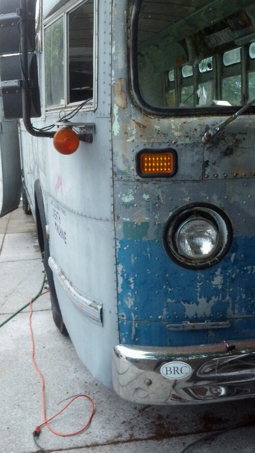
The previous owners had removed the factory front turn signals and since the originals are  impossible to find, I decided to install LED rectangular signals (closest match I could find that was reasonably priced). This required sawing a hole in the old turn signal ‘cover’ metal that someone had installed. Once that was finished, the lights simply popped into these holes and connection is made behind the dash and in the passenger side jockey box. It should be noted that using these locations requires some modification of the drivers side windscreen wiper bracket to allow the rather deep lights to fit far enough into the body to properly seat in the rubber grommets. Thinner fixtures would solve this problem as well.


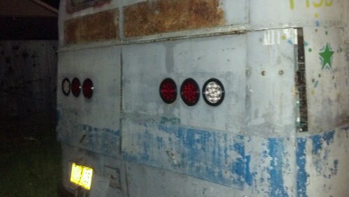
The rear lighting simply required moving the old incandescent fixtures, adjusting hole sizes, and mounting the 4″ round fixtures and their associated grommets. Since these are all LED lights, power consumption is so low that smaller new wiring is being run to feed the lights/relays for trailer connection. A LED compatible turn signal flasher is also required (cheaply available on Amazon/etc.)


The stock rear lighting configuration (two small fixtures down low on the body) looks cool but functionally I’d expect people to smash into the back of The Ghost regularly if that is all the lighting I had. The previous owners installation of x4 brake/tail and x2 turn signals looks tacky but is very effective at catching people’s attention (even over motorcycles/etc. mounted on the rear). With the LED conversions installed, things are VERY bright back there when on the stop pedal.

Steel armored side marker/turn signals were mounted low down on the side of the body (amber mid, amber front, and red rear) to provide the requirements for NTSB. These also aid greatly (properly connected) to indicate when executing a lane change if someone is sitting along-side the coach. To make this work, the side LED lights simply are connected one wire to tail light power, one wire to turn signal power. Resistors may be required depending upon the internal makeup of the lights, but this works nicely to help get cars out of the way when on the freeway. Lights were sourced off Ebay (Optronics model MCL86RB)

Overhead clearance lighting is functioning currently and since I recently sealed all the fixtures to the roof, I am inclined to continue using them but swap out the bulbs with LED conversions. I would only be tempted to replace these if I was able to source the original large clearance lights found on the bus in the 50’s (unobtainium). No rush on these.

Retro-reflectors are being mounted in all positions where the associated marker/turn/tail light doesn’t already have them built in. There are a few other locations that require a retro-reflector so I will add as necessary. These are very effective at lighting the coach in the event of a on-road power failure or when parked to prevent getting smashed into.


Overall fairly pleased with the conversion. It will be nice to leave marker lighting on when doing deep desert camping to prevent collisions without worry of draining down the battery.


Shes home!

The Ghost made the first trip since transmission work and made it to the new home DAS BREMHAUS! Lots of freeway onramp power and with the ‘audiable’ new exhaust, people stay out of the blind spot.


Exhaust Upgrade

Something long overdue for work, mostly back-burnered because it wasn’t outright dragging on the ground, was the existing exhaust system. The stock dual 3 into 1 manifolds with matching  <3″ piped canisters + flexible rusty crushed pipe just wasn’t cutting it. The Ghost’s exhaust was quiet enough, but cruising down the highway I had a feeling the back-pressure was high and the restriction too much to let the engine stretch out. I sourced some 5″ exhaust components, installed an industrial 6 into 1 (4″) manifold, and built up a custom system.


The industrial manifold (which you usually see mounted upright) points down off the back of the cylinder head with the outlet pipe parallel to the engine block. I installed an immediate 4″ to 5″ adapter at the output flange. From there it travels downwards about 10″ and then bends (about 85 degrees from straight) towards the front of the bus. Usually there is a bulkhead here (aluminium) however I cut out a 8-9″ round hole to allow the pipe to pass through without touching or rubbing. It them immediately makes a turn to the drivers side of the coach, where it connects with the 5″ resonator and drops out close to the ground through a 5″ turn-down. I lightly sectioned a undercarriage panel (non structural) so that the turn-down fit nicely up into the body without hanging out the breeze (making the coach wider) or being even closer to the ground. The end result turned out excellent and shy of installing a few rubberized exhaust hangers, the setup is done. A slip-joint coupling was used at the pass-through of the bulkhead; everything else being welded solid. The flange obviously unbolts from the manifold as well.

The end result is a very aggressive high flow exhaust. There is room for improvement in the overall noise level department, but the note is acceptable and we’ll see how it sounds on a long run. A longer muffler can could be installed in place of the shorter one if needed. It definitely lets you know it is a 426cu in 2-stroke…rat rod style.


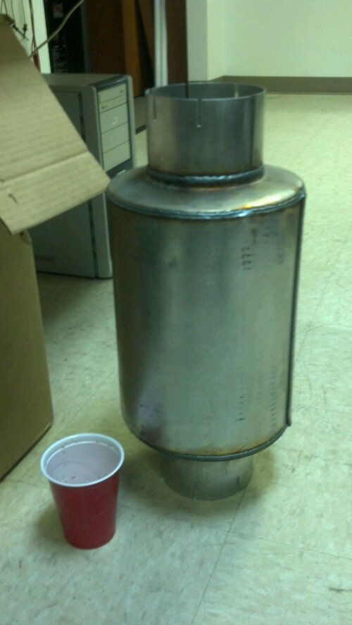
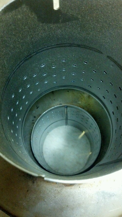
A size photo comparison of the purchased 5″ muffler.

image


As you can see, it is a direct pass-through design with two resonant perforated sections at the inlet/outlet and a open area in the middle.

image


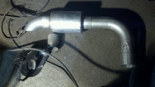
Here is a photo of the piece that connects (at the bulkhead) to the rest of the exhaust up to the engine.

image


While I was doing this task, I took the opportunity to do an acid was on the cooling system. I had seen scale buildup evidence in my coolant buckets/samples so, figuring it hadn’t be done in quite some time, gave it a strong shock of Oxalic acid for a few runs up and down the road. I then drained, flushed multiple times, and re-filled with my coolant.

image


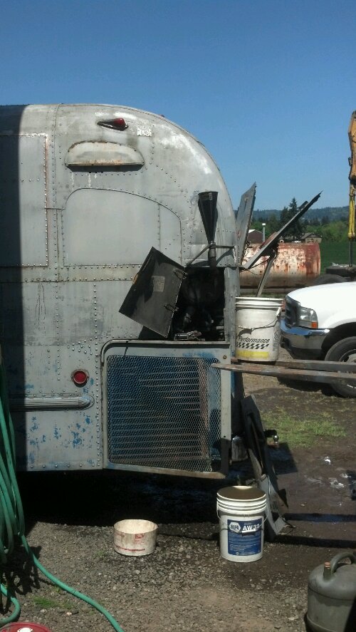
The handy trick for filling a horizontal radiator cap which is eye level from a 5-gal bucket. Funnel + flexible hose + bungee cord + forklift.

image


All in all a very productive Saturday. I took a break from the work for Mothers Day and will resume re-assembling the sheet metal back onto the rear of The Ghost so it can make it’s trip over to the new house Emily and I are closing on this week.


Until next time…

VS2-8 Transmission O/D Repair – Finished! & Powertrain Update

Well, it’s been multiple weekends and week nights working hard to get it fixed, but the VS2-8 transmission in The Ghost is now back to operational status.


A few short (<5mi) test drives were performed however with an unfinished exhaust system, things are a little too loud to be driving far. All three ‘gears’ were fully functioning and after topping off the transmission fluid (being careful not to overfill) shifts were firm.

There still remains the need for a microswitch on the throttle linkage to enable the soft down-shift solenoid for O/D to direct drive. I also want to fine-tune the shift point into O/D as currently the switch happens at about 40MPH and I would prefer it to be closer to 52MPH. I am also planning to install a small fluid/air transmission cooler and some valves for switching between O/D and Direct Drive (manual mode).

Another large hurtle overcome was getting the engine power up to rated output. Apparently making the timing adjustment as well as re-adjusting all injectors/exhaust valves with doing a full rack run/setup procedure really brought the power output up. The ‘new’ governor cover with shutdown lever that I had been fighting (and discovered was limiting fuel travel) had been adjusted to no longer interfere. With this fixed, the rack tuned normally and the idle, high speed, and full fuel adjustments were 10 times easier. Seat-of-the-pants power output feels considerably better than before. With overdrive fixed, MPG should improve as well.


The positive to negative ground conversion is going well. The generator and the regulator (stock) both operated properly once I re-polarized the generator with negative ground. The dash gauges indicated charging status and everything except the positive ground gauges I disconnected is still working. I still need to fabricate a dash, re-wire the heater coolant pump motor (swap wires), and install all the engine/transmission gauges/speedometer. It appears there will be 1 speedometer gauge + 8 aux gauges spots:

  • Speedometer (0-85MPH)
  • Engine Oil Pressure (0-80psi)
  • Engine Water Temperature (0-250F)
  • Fuel Level
  • Transmission Temperature (0-400F) – 2 senders
  • Transmission Pressure (0-150psi)
  • Air Pressure (dual needle, indicate tank + application)
  • Charge Current (stock for now)
  • 1 slot left for a 2nd air pressure gauge if I go dual circuit air brakes

This weekend the plan is to fit the 5″ exhaust + muffler and route properly through the bulkhead. a 4″ to 5″ adapter is used at the industrial manifold (4 bolt) then it travels down along block, turns forward towards the bulkhead, passes through (need to cut a large hole) and bends to meet the muffler (if it won’t fit before this) and then finally dumps on the drivers side just behind the rear wheel with a 5″ turn-down. Makes for a total of ~170 degrees of 5″ mandrel bend (minus turn-down). The muffler is a straight-through resonator (Walker 21835). It will be a little loud, however I did not have enough space for a full size can in 5″ and I’d rather have less restriction than quiet exhaust (30ft from the drivers seat). I may fashion some sort of adapter to install on (or in place of) the turn-down for on-playa use to prevent stirring up playa dust from exhaust flow.


Another time lapse video from last nights work:

http://youtu.be/sWGKtlHKt-g

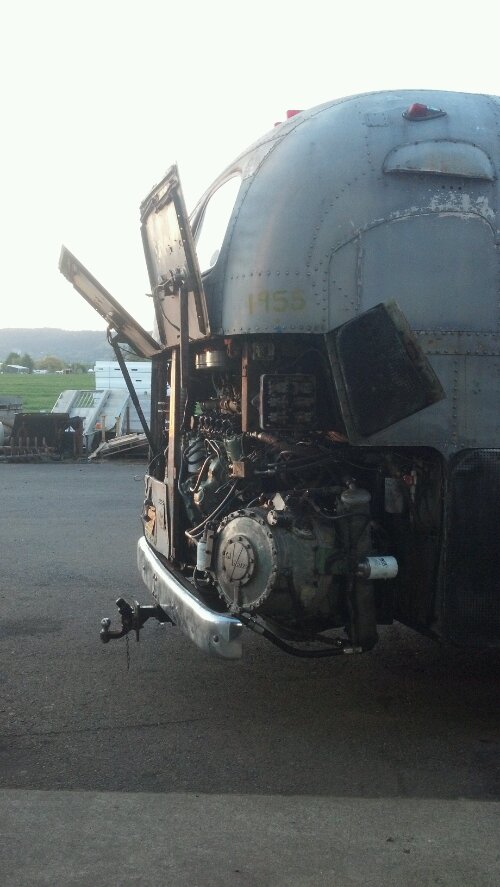
A photo before I put the valve cover and corner support rod back on for final road test.

image