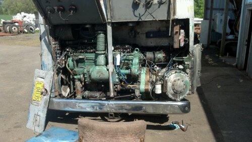
Another weekend, more things checked off the drivetrain list.
The big project for this weekend was to prepare the engine for the transmission reassembly and reassemble the transmission splitter overdrive clutch pack and planetary to make sure there were no hidden problems waiting to be discovered.
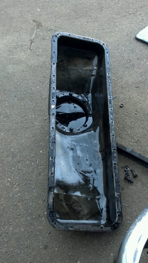
Part of removing the end housing off the engine is needing to replace the (leaking) oil pan gasket. This involves removing the oil pan from the coach, cleaning, and reinstalling with a new gasket. Seems easy however the maze of underbody cribbing and structure keep the puzzle adequately difficult. It was also suspected that there was a bunch of foreign material in the oil pan, after discovering the chunk of material wedged up against the main crank gear from an old air compressor drive failure.
Here is a photo of the oil pan just after removal. You can see the amount of foreign material in the pan (which should only contain motor oil)
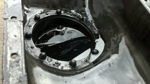
Here is a close up photo of the sump. Note the lack of cleanliness!
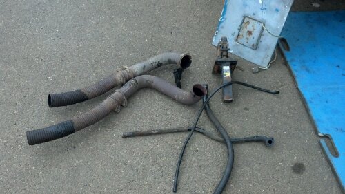
While in this area, I decided to remove the entire exhaust system to allow for the installation of my much simpler and (hopefully) better flowing 4-5″ exhaust system. These, shy of the flex, are probably stock setups. Both of the brackets that hold the mufflers to the oil pan area were loose, causing wear points on the oil pan (eventually would have worn through the pan, causing a massive leak). The mufflers themselves were starting to show signs of wear as both input and output pipes were starting to rattle loose and leaking exhaust. Time for replacement.
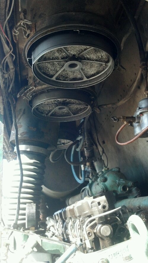
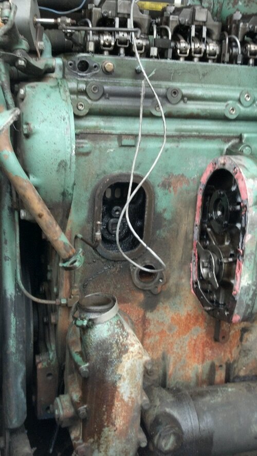
Here is a photo of what you often don’t see. The air-box cover has been removed (to replace the gasket) and the governor housing, flyweights, water pump, and blower end housing to allow for replacement of a gasket that was leaking oil. I was in here recently (August 2011) to inspect issues with the governor when I discovered the water pump drive had failed. Unfortunately I didn’t have the correct gasket to do the job, so some Three Bond + Gaffing Tape saved the day for the trips. Upon R&Ring this area, I found that there was yet ANOTHER piece of water pump drive plastic laying in the sump where it didn’t belong. Apparently it had been hiding behind something and didn’t get removed when I replaced the drive. Bottom left is oil to water cooler, and bottom right is the oil filter housing.
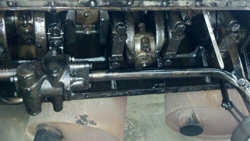
Here is a photo of the bottom of the engine (oil pan removed) you can see the oil pickup tube as well as the main bearing caps and connecting rods. These parts are NOT small. The dipstick is visible on the right side of the photo.
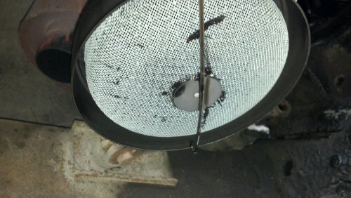
This is the material that was stuck in the oil pickup screen. There were many more small particles stuck in the screen itself (not visible here). Fortunately this piece is EASILY cleanable and accessible without removing the whole oil pan (a lower sub pan removes for easy access). The Ghost has a full flow oil filter so luckily none of this stuff made it into the bearing surfaces.
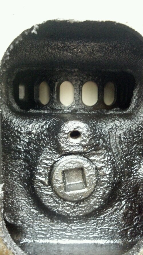
Here is a photo in the air-box with the cover removed. You can see (through the air intake holes) the skirt of the piston. It is in fairly good shape. This space is showing the miles but there is no accumulation of moisture which means the air-box drains are clear. This space is pressurized at all times the engine is running to force air out of the combustion chambers on the down stroke (end of power and beginning of exhaust). This is a 2-stroke diesel engine (every stroke of the piston is a power stroke).
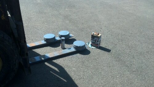
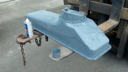
Although this LOOKS Alpine Green, it is actually dark grey paint that I happened to have on hand to paint the paint-less gross oil pan, post cleaning.
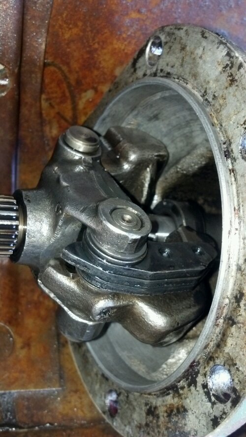
Here is a close up shot of the governor housing flyweights. These flyweights, in conjunction with the springs in the governor box, regulate engine idle speed and maximum engine RPM. They are fed rotational energy off the end of the blower housing (just above the water pump).
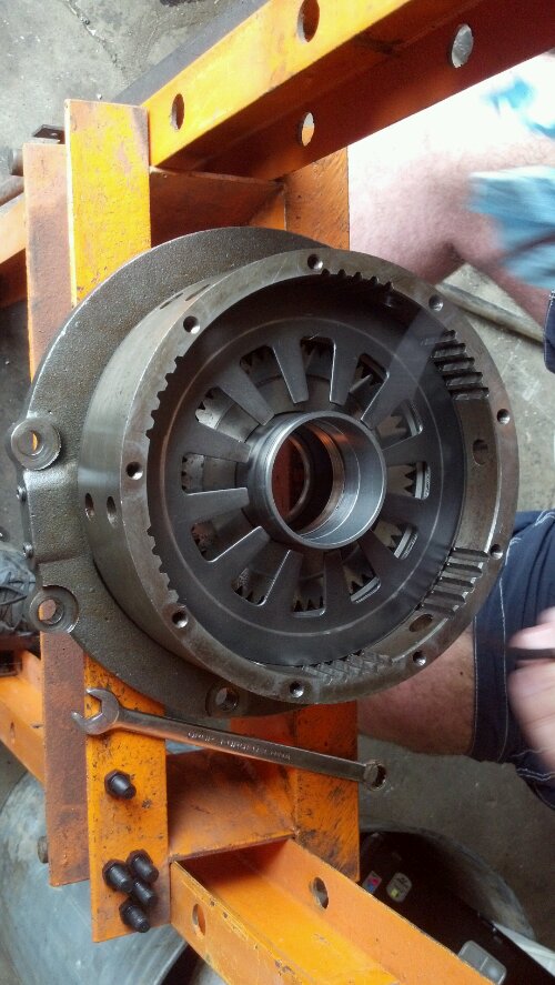
Here is a photo of the splitter overdrive clutch housing being assembled. The top of this stack is the bellville spring which translates the piston movement into an actual clutch pack movement (and thus, a shift).
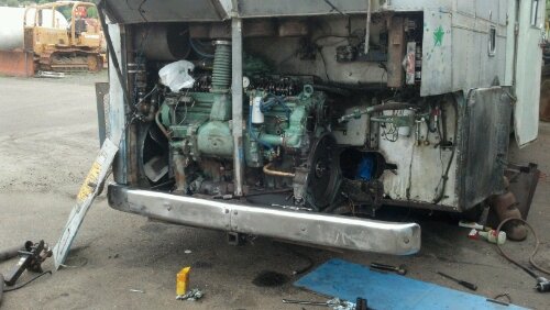
A photo of the now MUCH cleaner engine after hours of pressure washing. Of primary ‘nasty’ was the engine mounting points below the transmission and the subframe components. I also discovered that my radiator was 1/3 plugged with foreign material in the cooling fins. Some Castol Superclean + HOT pressure washer water cleared things outs nice (don’t do this at home, you likely will damage the radiator fins). It is amazing that the engine didn’t overheat more readily with the amount of plugging it was experiencing. A minor oil leak at the oil pan and compressor housing caused most of the engine to the right of the roots blower to be coated with dirt + oil + playa dust so thick that only the high pressure spray would tear it loose. The engine block actually now needs a good coat of Alpine Green to finish it off.
Here is a progress photo of the transmission after installing the splitter overdrive clutch pack. This setup is now ready for the planetary + outer gear before installation. Some plumbing rework will be done as well as dropping the pan to gather all the last metal bits and whatnot that fell down in there. The factory installs a large magnet in the pan so I’m expecting that to be quite built up with shards. The flywheel, with the new bushing installed in visible in the bottom right side of the photo. The two spacer rings required for a 6-71 to VS2-8 mating are visible on the left of the photo.
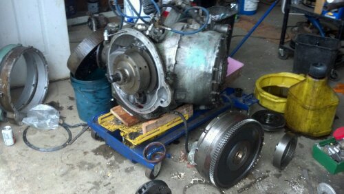
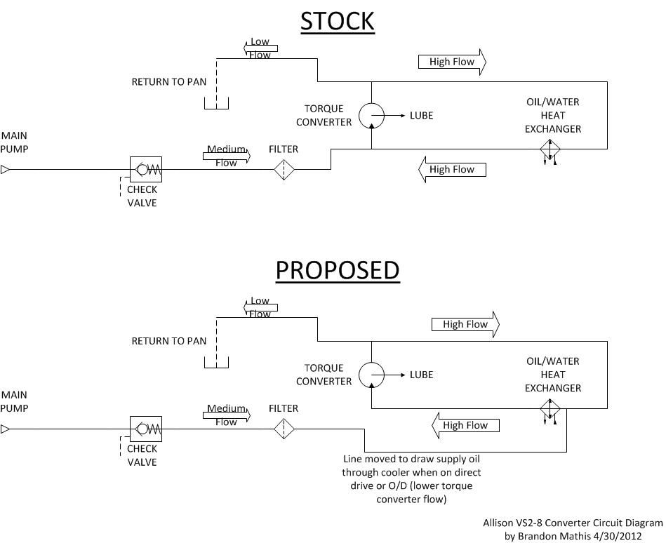
It was a very productive weekend and after a few more hours of cleaning up the last bits, the transmission should be ready to install and start building the supportframing that I have needed to build all this time. A medium size external oil cooler will also be fitted to help keep the transmission cool in the direct-drive/over-drive mode where not much fluid passes through the cooler.
More soon.
