Detroit 6-71 Valve, Injector, and Governor Adjustment Procedure
Enjoy

Another weekend, more things checked off the drivetrain list.
The big project for this weekend was to prepare the engine for the transmission reassembly and reassemble the transmission splitter overdrive clutch pack and planetary to make sure there were no hidden problems waiting to be discovered.
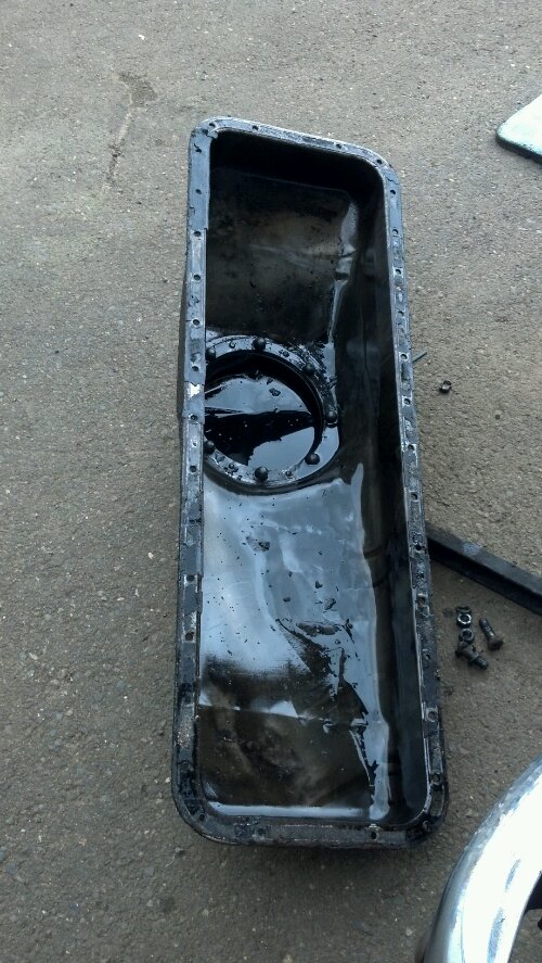
Part of removing the end housing off the engine is needing to replace the (leaking) oil pan gasket. This involves removing the oil pan from the coach, cleaning, and reinstalling with a new gasket. Seems easy however the maze of underbody cribbing and structure keep the puzzle adequately difficult. It was also suspected that there was a bunch of foreign material in the oil pan, after discovering the chunk of material wedged up against the main crank gear from an old air compressor drive failure.
Here is a photo of the oil pan just after removal. You can see the amount of foreign material in the pan (which should only contain motor oil)
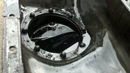
Here is a close up photo of the sump. Note the lack of cleanliness!
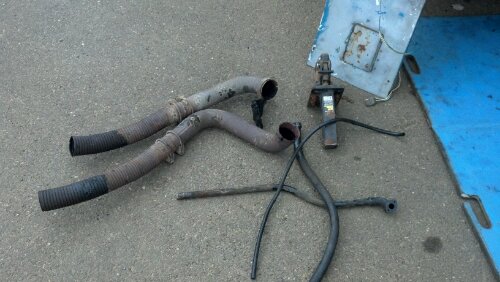
While in this area, I decided to remove the entire exhaust system to allow for the installation of my much simpler and (hopefully) better flowing 4-5″ exhaust system. These, shy of the flex, are probably stock setups. Both of the brackets that hold the mufflers to the oil pan area were loose, causing wear points on the oil pan (eventually would have worn through the pan, causing a massive leak). The mufflers themselves were starting to show signs of wear as both input and output pipes were starting to rattle loose and leaking exhaust. Time for replacement.
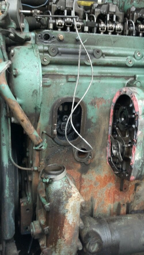
Here is a photo of what you often don’t see. The air-box cover has been removed (to replace the gasket) and the governor housing, flyweights, water pump, and blower end housing to allow for replacement of a gasket that was leaking oil. I was in here recently (August 2011) to inspect issues with the governor when I discovered the water pump drive had failed. Unfortunately I didn’t have the correct gasket to do the job, so some Three Bond + Gaffing Tape saved the day for the trips. Upon R&Ring this area, I found that there was yet ANOTHER piece of water pump drive plastic laying in the sump where it didn’t belong. Apparently it had been hiding behind something and didn’t get removed when I replaced the drive. Bottom left is oil to water cooler, and bottom right is the oil filter housing.
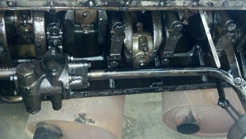
Here is a photo of the bottom of the engine (oil pan removed) you can see the oil pickup tube as well as the main bearing caps and connecting rods. These parts are NOT small. The dipstick is visible on the right side of the photo.
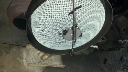
This is the material that was stuck in the oil pickup screen. There were many more small particles stuck in the screen itself (not visible here). Fortunately this piece is EASILY cleanable and accessible without removing the whole oil pan (a lower sub pan removes for easy access). The Ghost has a full flow oil filter so luckily none of this stuff made it into the bearing surfaces.
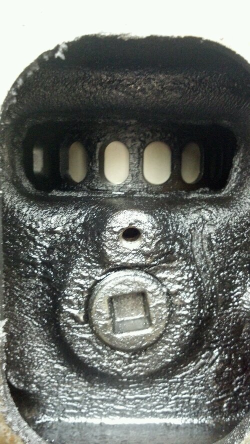
Here is a photo in the air-box with the cover removed. You can see (through the air intake holes) the skirt of the piston. It is in fairly good shape. This space is showing the miles but there is no accumulation of moisture which means the air-box drains are clear. This space is pressurized at all times the engine is running to force air out of the combustion chambers on the down stroke (end of power and beginning of exhaust). This is a 2-stroke diesel engine (every stroke of the piston is a power stroke).
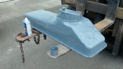
Although this LOOKS Alpine Green, it is actually dark grey paint that I happened to have on hand to paint the paint-less gross oil pan, post cleaning.
Here is a close up shot of the governor housing flyweights. These flyweights, in conjunction with the springs in the governor box, regulate engine idle speed and maximum engine RPM. They are fed rotational energy off the end of the blower housing (just above the water pump).
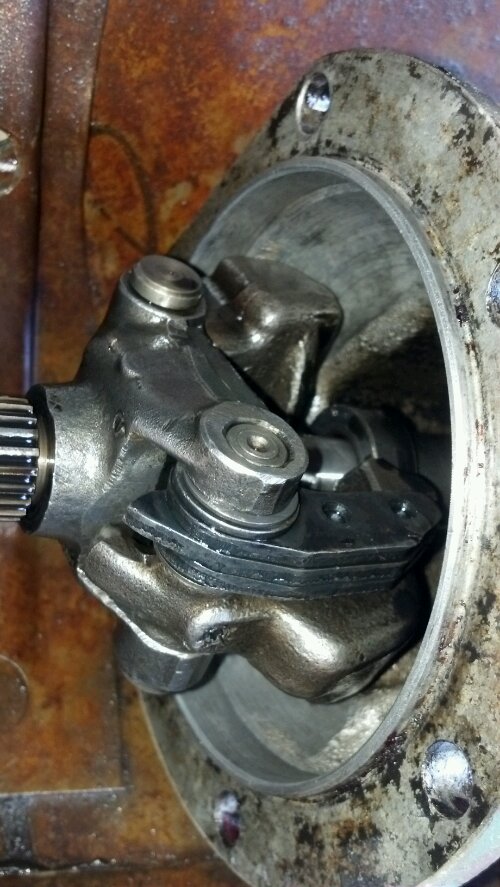
Here is a photo of the splitter overdrive clutch housing being assembled. The top of this stack is the bellville spring which translates the piston movement into an actual clutch pack movement (and thus, a shift).
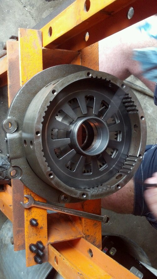
A photo of the now MUCH cleaner engine after hours of pressure washing. Of primary ‘nasty’ was the engine mounting points below the transmission and the subframe components. I also discovered that my radiator was 1/3 plugged with foreign material in the cooling fins. Some Castol Superclean + HOT pressure washer water cleared things outs nice (don’t do this at home, you likely will damage the radiator fins). It is amazing that the engine didn’t overheat more readily with the amount of plugging it was experiencing. A minor oil leak at the oil pan and compressor housing caused most of the engine to the right of the roots blower to be coated with dirt + oil + playa dust so thick that only the high pressure spray would tear it loose. The engine block actually now needs a good coat of Alpine Green to finish it off.
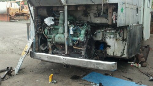
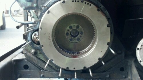
Here is a progress photo of the transmission after installing the splitter overdrive clutch pack. This setup is now ready for the planetary + outer gear before installation. Some plumbing rework will be done as well as dropping the pan to gather all the last metal bits and whatnot that fell down in there. The factory installs a large magnet in the pan so I’m expecting that to be quite built up with shards. The flywheel, with the new bushing installed in visible in the bottom right side of the photo. The two spacer rings required for a 6-71 to VS2-8 mating are visible on the left of the photo.
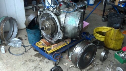
It was a very productive weekend and after a few more hours of cleaning up the last bits, the transmission should be ready to install and start building the supportframing that I have needed to build all this time. A medium size external oil cooler will also be fitted to help keep the transmission cool in the direct-drive/over-drive mode where not much fluid passes through the cooler.
More soon.
For day two, while waiting on transmission parts, I decided to do some work on the engine while the transmission is off and things are ‘relatively’ accessible. There has been an ongoing suspicion that the engine timing was set to standard (versus the now accepted desired setting of advanced).
To remove this part of the engine, it must be supported as the motor mounts connect to this piece. We used a forklift with two bolts on the lifting eye bolted into the cylinder head. There are numerous bolts that hold the housing to either the block or to the plate (which bolts to the block)
As it turns out, the engine was set to standard timing. This was corrected. We also found that at some point in the past an older style non-metallic compressor drive (center of upper-left gear) had busted into pieces and some had fallen down into the housing. We discovered a fairly large piece and expect to find more in the oil pan. The drive has since been replaced with the newer steel type so that shouldn’t be a problem again.
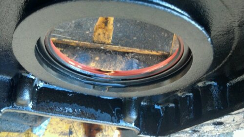
It was also discovered that a single-lip rear main seal had been installed when a double-lip is more appropriate with a wet bellousing (transmission fluid). Fortunately the crank journal where the seal seats is in very good condition so a wear sleeve and oversize seal is not required. The paper-gasket was high-tack adhered to the block/plate and Permatex Aviation Form-a-Gasket was applied to the paper gasket before bolting the housing back on. The oil-pan still needs to be removed to apply a new gasket and clear out any old paper gasket/pieces of the drive coupling from before.
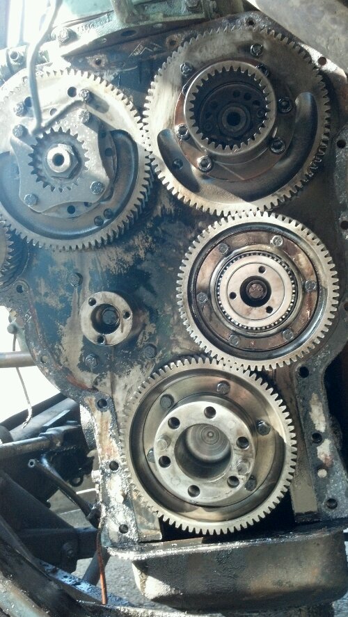
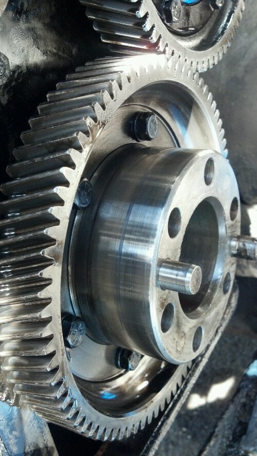
Photo of the cam/balance shaft gears (generator drive on the right, air-compressor drive on the left)
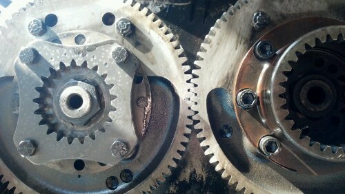
A close-up of the timing marks to indicate when the balance shaft and camshaft is in-time.
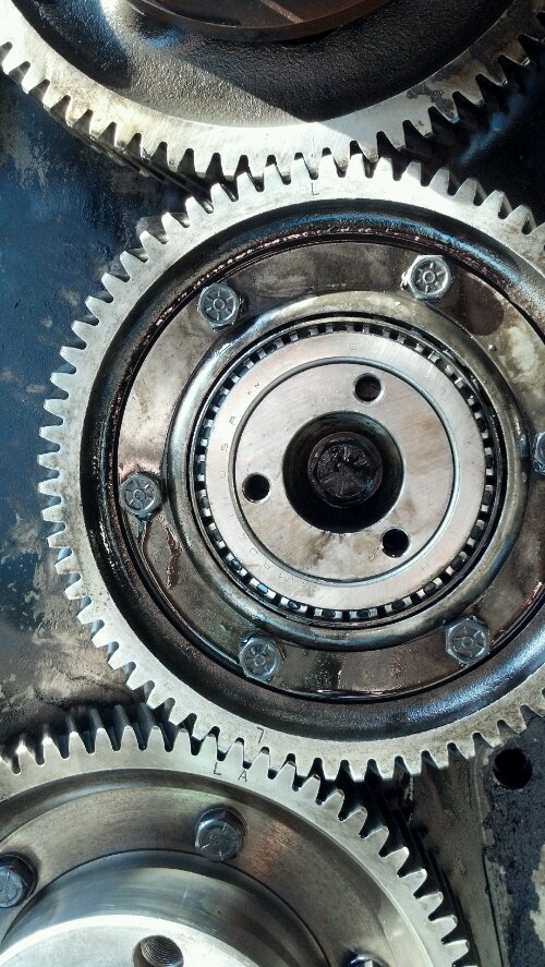
Post-Adjustment showing the L mark lining up with the A mark. Previous L was with L (left standard to left mark). This was changed by removing the idler gear (bolt in the center) and rotating the cam/balance shaft combination to give one tooth advance.
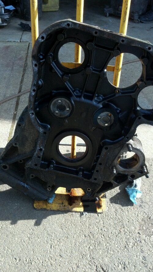
This is the cover, removed from the engine, needing the old gasket scraped.
Here is a close-up photo of the sealing surface for the rear main seal.
The old rear main seal (single lip) before removal.
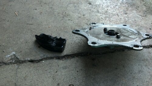
On the left, the piece of material we found in the housing rubbing up against gears. On the right, the cover for the tachometer drive and blower end)
The next big step for this project will be removing/cleaning/re-installing the oil pan gasket (both upper and lower). With all the cross-members under the coach, this will be rather annoying but it has to be done. The transmission parts will hopefully arrive sometime this week or early next week so I can get started on bolting the transmission back together and preparing for re-installation. New style filters and an external oil cooler will be fitted (GM style transmission cooler for their full size pickups). I am also toying with installing a full-flow cooler for the torque converter circuit. We will see how much space is available for these modifications (the transmission already rubs on the passenger side engine bay door.
All-in-all finding the timing off made the tear down worth while. It also put me at piece of mind because (shy of the oil pan) this was the last piece to remove that could have had ‘hidden stuff’, like broken non-metallic drive parts (last year found that the water pump drive was failing as I was servicing the governor flyweight housing and also had the air compressor drive (compressor side) fail while at SOAK 2011. The timing adjustment should give the engine a little more pep and with a fresh rack run-up, it should bring the power and torque up to snuff.
Thanks for checking in.
Today’s summary of findings. Carnage.
I decided to spend this Easter Sunday removing the limited operation damaged VS2-8 from The Ghost to investigate the issue behind loosing overdrive (see earlier posts). The bus still ran and drove, but didn’t shift into that awesome gear when fuel MPG surpasses 10 and the engine purrs rather than screams. Below is what I found.
Here is a simple shot of the transmission removed, studs still doing their job just as I installed them some 8-9 months ago.
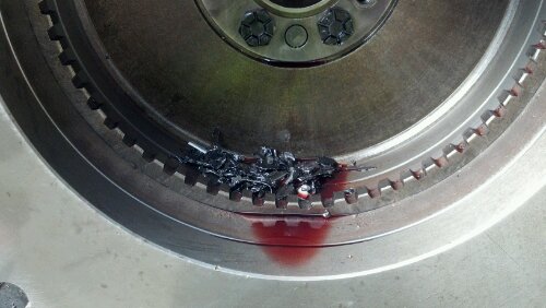
Here is the first thing I found after removing the transmission. That is mostly steel, some brass.
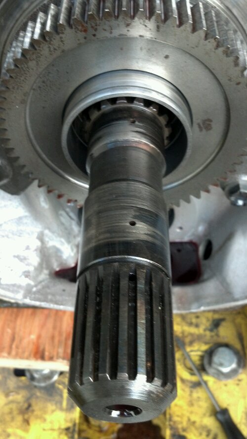
After spending some time removing the planetary (pictures below) and other associated clutch components, I was finally down to the input shaft (which carries lubrication). It is scored, but not terribly. Not sure if a series of loose bushings is to blame for bad lubrication…but something failed. Big time. The three holes are where the lubrication oil comes out to keep things happy. The hollow cylinder in the center of the gear is the piston itself that engages O/D or direct drive.
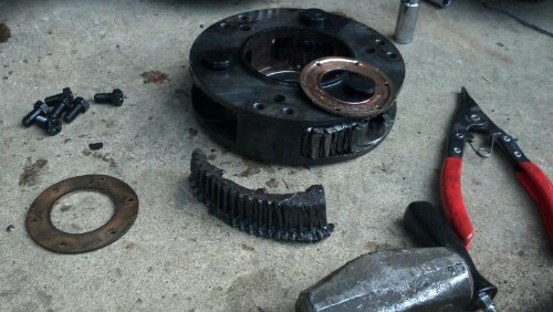
Now for the juicy photos. This is the planetary that I removed from the transmission that we drove (post failure) from Kalamath Falls, OR; to Gerlach, NV; and back home to Portland, OR. The planetary gears (three) are unrecognizable and one has been torn open and flattened out. One other was significantly damaged in a similar fashion, and the third was so hogged out internally that it flopped on it shaft pin. Also a bushing was smoked off.
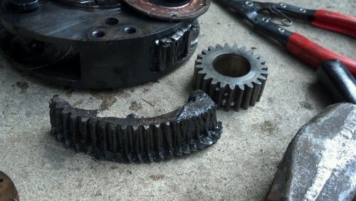
Here is an example of what the gear should look like, next to the most impressively damaged one. Excuse the styrofoam peanuts in the example gear.
Here is a photo of the associated sun gear (center of the planetary setup for overdrive). As you can see, it received some significant TORQUE at one point in it’s operation. Significant failure here, those teeth are supposed to be straight, not sloped.
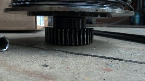
FORTUNATELY, these parts appear unharmed (seals coming in the mail to further inspect any issues inside here. This is mainly a large cast piece (fixed) and internally the piston setup for the O/D clutch pack. I never doubted this was working (and judging by the internal hogging of those planetary gears, I’d say that sun gear was doing just fine tearing up a clear path for it to spin or stop as it desired.
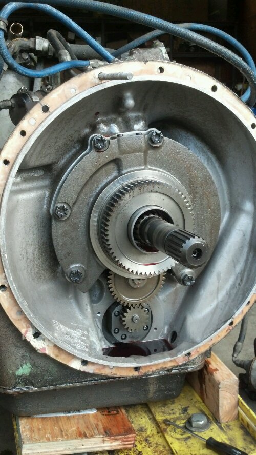
The basic summary here is that SOMETHING caused the planetary/sun gear setup to take itself out. We suspect inadequate lube oil or poor lube quality. This could be caused by a myriad of issues, but highest on my list so far is an overfull condition causing frothing of the oil, which caused shear issues within this housing.
It appears no metal passed through the pump (as the rest of the transmission kept working) and the exceptional number and size of filters on this transmission kept us going down the road without taking the rest of it out. I definitely need to drop the pan and inspect for any and all metal gear chunks that made their way down there. Also on the list is to figure out if actual lack of lubrication was the culprit and if so, how to modify that shaft/pinhole setup to aid in proper lubrication so this won’t happen again.
A very awesome fellow (Bill from Canada) graciously sent me some (if not all) of the hard iron parts that I need to fix this situation. That saves me having to purchase a $500-1000 transmission just to steal the O/D setup off of. These parts, with some new wear components (seals/bushings) should have me off and running again in no time. I intend to remove the end housing off the engine (which involves removing the air compressor, starter, generator, oil pan, and some other tidbits) so that I can check to see where the timing is set. Other than the front cover area (which is much less complicated), I have had this entire engine basically apart after this adventure.. At least the oil leaks are starting to disappear.
Feel free to comment on the carnage photos. I also have a time-lapse of some of the removal process from my Go-Pro that I need to format into video form. Mostly just downloading brain knowledge here while it is fresh.
Later!